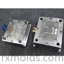
Automotive lighting components combine functional requirements with complex optical geometry and demanding appearance standards. From lenses and reflectors to housings, light guides, and decorative elements, these parts depend heavily on accurate tooling. A professional Automotive Lighting Mold Manufacturer must consider optical structures, material behavior, cooling, ejection, machining accuracy, and surface finishing throughout the mold development process.
The tooling process begins with a detailed evaluation of the component design. Modern lamp parts may include curved surfaces, thin walls, mounting structures, ribs, clips, sealing interfaces, and finely patterned optical features. Each element can affect the cavity layout and material flow. Engineers therefore need to review draft angles, parting lines, gate positions, ejection points, and cooling arrangements before manufacturing begins.
Material selection is closely connected with mold engineering. Transparent and translucent polymers used in lenses or light guides require carefully controlled cavity surfaces because imperfections may influence appearance or optical behavior. Structural lamp components may require different material characteristics, such as impact resistance, dimensional stability, thermal resistance, or chemical compatibility. Understanding these properties allows engineers to develop tooling around the intended material.
Mold flow simulation provides useful information during the early design stage. Engineers can examine how molten polymer may travel through the cavity and identify potential filling imbalance, weld lines, air entrapment, pressure concentration, or deformation. This information can support adjustments to gates, runners, venting, and other mold features before physical machining begins.
Optical cavity surfaces require particularly careful manufacturing. A lamp lens may contain micro-patterns, curved structures, or distribution features that influence the direction and spread of light. These details need to be transferred accurately from the mold to the molded component. CNC machining can establish complex three-dimensional geometry, while EDM may be applied to intricate or difficult-to-machine sections.
Surface finishing is another important stage. Depending on the component, different cavity areas may require polishing, controlled texturing, or other finishing treatments. Optical surfaces generally demand especially consistent preparation, while cosmetic areas may require a defined appearance. Careful inspection during finishing helps ensure that the cavity remains consistent with the approved design.
Cooling design has a direct effect on molding stability. After the polymer enters the cavity, heat needs to be removed at an appropriate rate before the component can be ejected. Uneven cooling can contribute to warpage, dimensional variation, or residual stress. Cooling channels should therefore be positioned according to the geometry and thermal behavior of the component rather than using a standardized layout.
Venting also plays an important role in filling quality. Air displaced by the incoming polymer needs to escape through suitable venting paths. Poor venting may contribute to burn marks, incomplete filling, or localized surface defects. Engineers should determine vent positions according to the expected flow pattern while protecting important visible and optical areas.
The ejection system must be designed around the structural characteristics of the lamp component. Deep cavities, thin edges, curved surfaces, and cosmetic areas can make part release more demanding. Ejector pins, sleeves, lifters, and other mechanisms should be arranged to distribute forces appropriately. Proper draft angles can also reduce resistance during demolding.
Precision inspection should continue throughout mold manufacturing. Cavity dimensions, core alignment, moving components, cooling passages, and surface conditions all need appropriate verification. During mold trials, engineers can evaluate filling behavior, dimensional accuracy, optical or cosmetic appearance, ejection performance, and assembly compatibility. Trial results provide practical information for controlled tooling adjustments.
Digital technologies help connect the various stages of development. CAD supports detailed mold construction, CAE provides simulation and analysis, and CAM translates approved geometry into machining operations. When these technologies are combined with practical manufacturing experience, complex lighting tooling can be developed through a more coordinated workflow.
Long-term tooling stability also depends on appropriate maintenance. Repeated production cycles can gradually affect moving mechanisms, cavity surfaces, alignment areas, and cooling systems. Regular inspection can help identify wear before it influences molded component quality and can support more predictable production planning.
For manufacturers developing complex vehicle lighting components, Taizhou Renxin Mould Co., Ltd. integrates mold design, simulation, precision machining, surface finishing, and tooling validation, with further information available at https://www.rxmolds.com for companies evaluating an Automotive Lighting Mold Manufacturer for professional automotive lighting projects.